SafeBricks India Private Limited Enquire Now
SafeBricks quality and safety construction standards

Quality & Safety

Built around quality.
Designed for safety.

A considered standard for structure, finishes, utilities, amenities and everyday residential comfort.

05Disciplines
23Specifications

01Civil, Structural, and Masonry Works

Structural Grid

Specification 01

Structural Grid

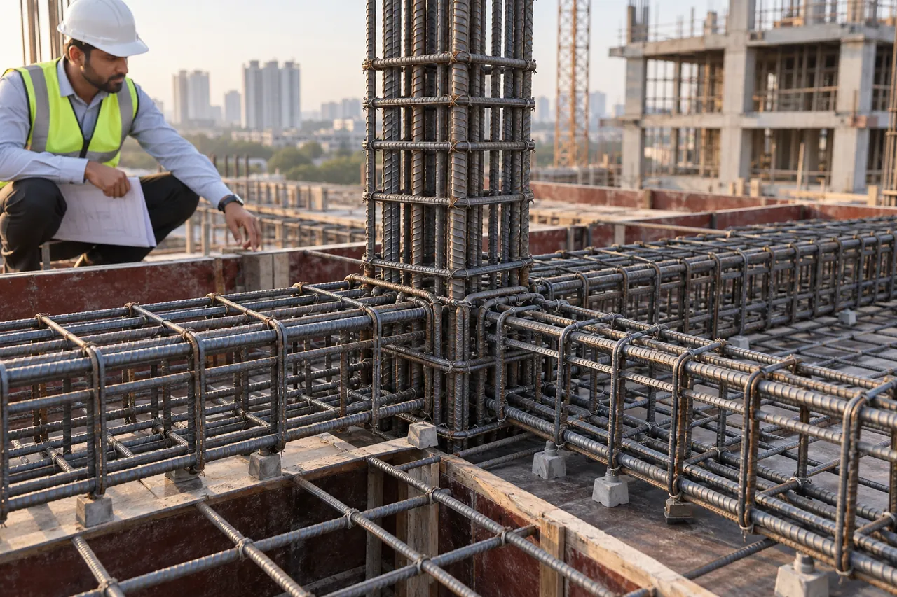
The building shall comprise an RCC framed structure, designed and executed in accordance with approved structural drawings and applicable Indian Standards. The specified Zone II seismic parameters shall be subject to confirmation by the structural engineer for the project location. Ready Mix Concrete (RMC) of M25 grade shall be used for structural columns, beams, slabs, and lintels, unless a higher grade is required by the approved structural design or exposure conditions. M25 denotes a characteristic concrete cube compressive strength of 25 N/mm² at 28 days. Concrete shall be supplied against an approved mix design, with controlled batching, transportation, placement, mechanical compaction, and curing. Quality checks shall include workability testing, concrete cube testing, and inspection of formwork and reinforcement before concreting. Foundation design, member sizes, and load-bearing requirements shall follow the structural engineer’s calculations and site soil investigation.

Steel Reinforcement

Specification 02

Steel Reinforcement

Primary structural reinforcement shall use Fe 550 Grade TMT Steel from Tata / Prime Gold / equivalent Tier-1 manufacturers, subject to approval of the exact product and its suitability for the structural design. Reinforcement shall conform to IS 1786, with manufacturer test certificates and material traceability maintained for supplied batches. Fe 550 and Fe 550D are separate grade designations; the required ductility properties shall be confirmed by the structural engineer. Bar diameters, spacing, lap lengths, anchorage, stirrups, and reinforcement detailing shall strictly follow approved drawings and bar bending schedules. Suitable cover blocks and chairs shall maintain the specified concrete cover and reinforcement position during casting. Steel shall be stored above ground and protected from contamination, with unacceptable corrosion or damage checked before installation.

Masonry & Plastering

Specification 03

Masonry & Plastering

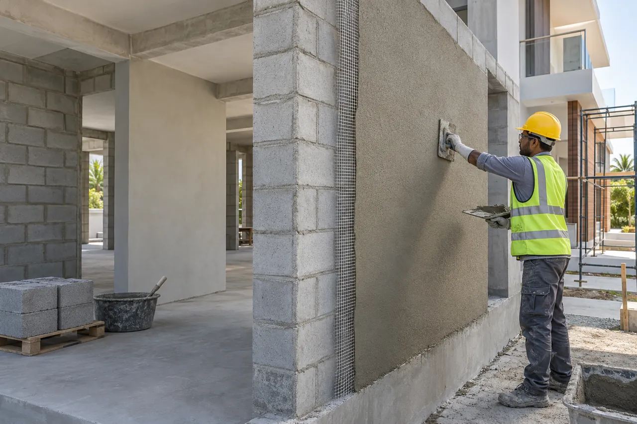
External walls shall be constructed using 6-inch solid block masonry, while internal partition walls shall use 4-inch solid block masonry, in accordance with approved architectural and structural details. Blocks shall meet specified requirements for strength, dimensions, and water absorption. Masonry shall be laid with approved mortar proportions, properly filled joints, suitable bonding, and consistent alignment, level, and verticality. Internal plastering shall use clean, properly graded M-Sand suitable for plastering, providing a smooth and even surface ready for subsequent wall finishing. External walls shall receive dual-coat waterproof sand-faced plastering, incorporating an approved waterproofing admixture or specified plaster system to reduce rainwater penetration. Surface preparation, treatment of RCC–masonry junctions, service chases, opening edges, and curing shall follow approved workmanship details to reduce cracking and improve adhesion. Plaster thickness and mortar proportions shall follow the project specifications.

Cement Baseline

Specification 04

Cement Baseline

Cement shall be ACC Romeo or an equivalent certified product, subject to confirmation of the exact product designation and approval by the structural engineer. The cement type and grade shall be selected for the intended use, including structural concrete, masonry mortar, and plastering, and shall comply with the relevant Indian Standard. Supplies shall be obtained from authorised sources, with manufacturer identification, batch details, and supporting quality documentation available for inspection. Bagged cement shall be stored in a dry, weather-protected area on raised platforms, away from direct contact with the ground and moisture. Stock shall be used in an orderly sequence, and material showing moisture damage, hard lumps, or deterioration shall be rejected or assessed before use. Cement substitutions shall require confirmation of compatibility with the approved concrete mix design, admixtures, and performance requirements.

02Openings, Joinery, and Fenestrations

Main Entrance Assembly

Specification 05

Main Entrance Assembly

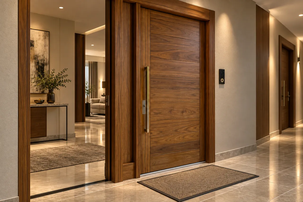
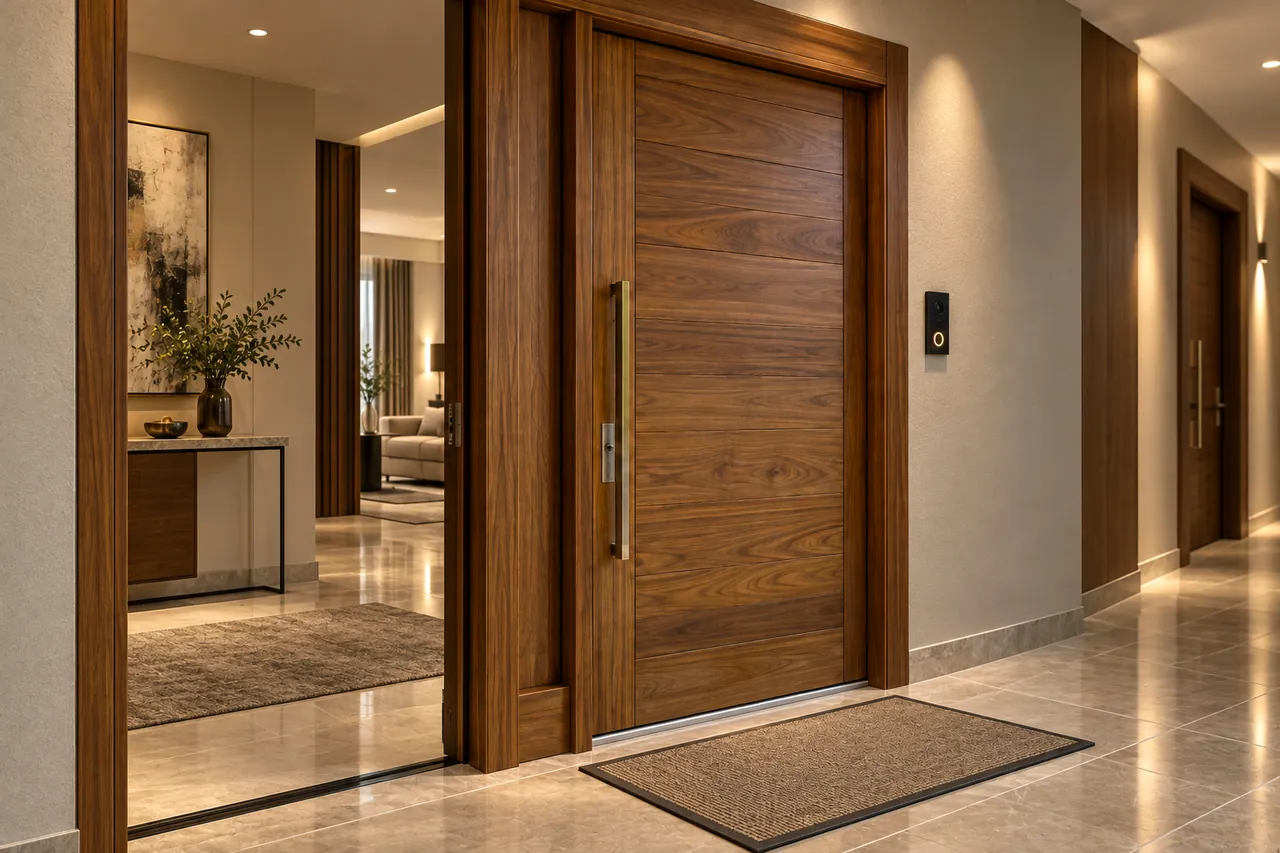
The main entrance shall feature a premium Teak Wood frame, with the stated dimensions of 6′ × 4′, paired with a solid Teak Wood shutter door. The separately specified 5′ × 3′ section profile, along with the intended measurement units, shall be confirmed against the approved door schedule before fabrication. Timber shall be properly seasoned and inspected for cracks, excessive knots, insect damage, and other defects affecting appearance or performance. The assembly shall include architectural security hardware comprising heavy-duty hinges, handles, a compatible multi-point locking system, and suitable door stoppers. Hardware shall be selected according to the shutter’s weight, thickness, and operating requirements. Frames shall be securely anchored, and shutters shall be installed with uniform clearances for smooth opening and reliable locking. Exposed timber surfaces and edges shall receive the approved protective finish, with particular attention to moisture protection at the bottom edge and frame–wall junctions.

Internal Room Openings

Specification 06

Internal Room Openings

All designated bedroom and living-area door openings shall incorporate waterproof and warp-resistant WPC (Wood Plastic Composite) frames, paired with flush shutters in accordance with the approved door schedule. Frames shall be selected for dimensional stability and adequate fixing strength, particularly at hinge and lock locations. Shutter thickness, core construction, moisture-resistance grade, and surface finish shall be specified separately to suit each location; the waterproof properties of the WPC frame shall not be assumed to apply to the flush shutter. Shutters shall receive approved laminate, veneer, or painted finishes, with edges and hardware cut-outs suitably sealed. Each assembly shall include compatible hinges, handles, locks or latches, and door stoppers. Installation shall maintain correct alignment, secure anchorage, and consistent operating gaps, followed by checks for rubbing, sagging, and satisfactory latch engagement.
Windows & Balcony Sliders

Specification 07

Windows & Balcony Sliders

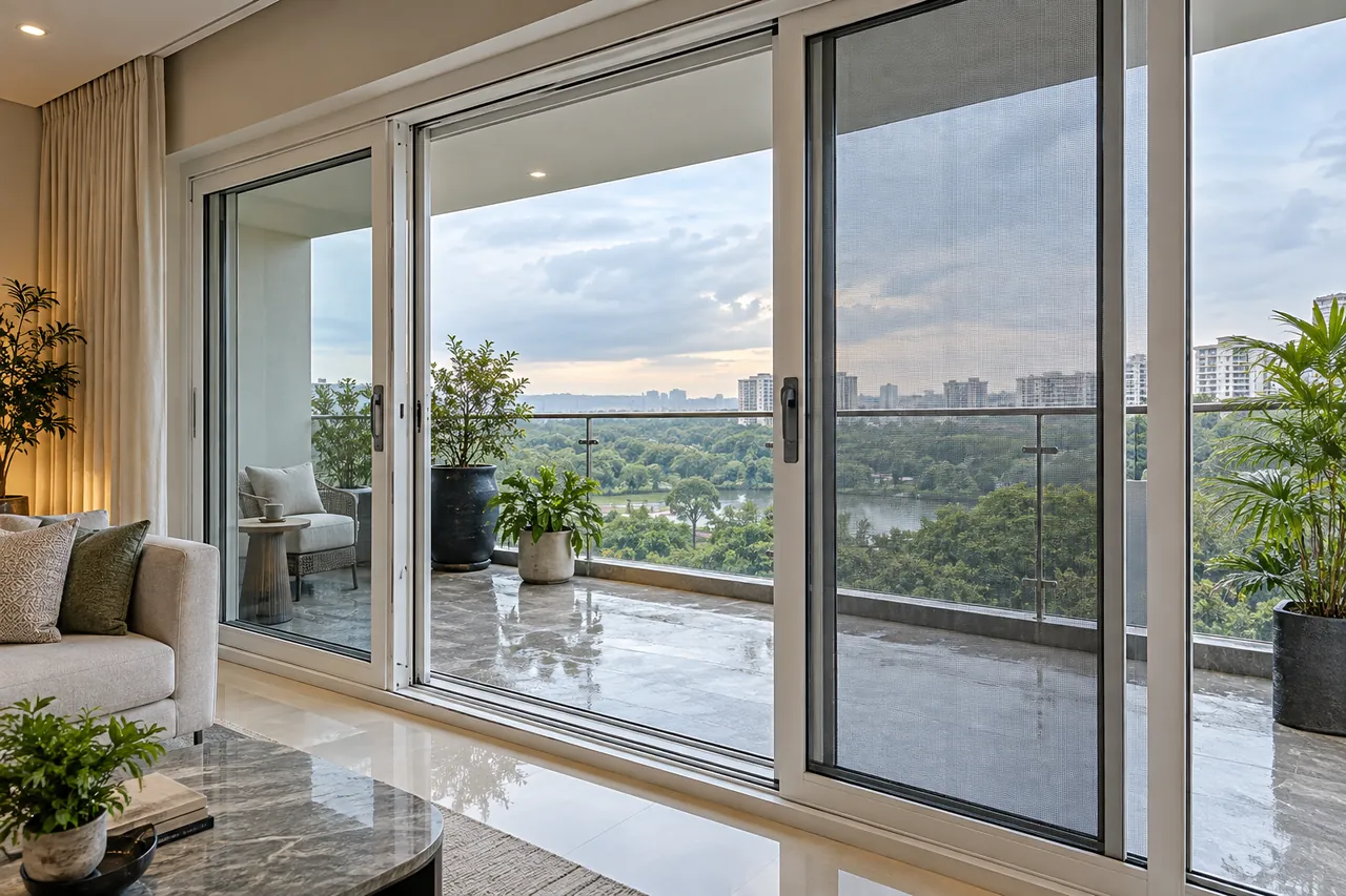
Windows and balcony openings shall be fitted with heavy-duty UPVC sliding windows and doors, incorporating clear float glass panels, integrated bug/mosquito mesh tracks, and premium hardware fittings. UPVC profiles and internal reinforcement shall be selected to suit the opening dimensions, shutter weight, and design wind loads. Glass thickness and safety treatment shall follow the approved glazing schedule, with appropriate toughened or laminated safety glazing specified for balcony doors and other locations requiring impact protection. Assemblies shall include suitable rollers, handles, locking devices, weather seals, and drainage provisions for smooth operation and controlled rainwater discharge. Mosquito mesh panels shall be removable or accessible for cleaning and maintenance. Frame perimeters shall be securely fixed and sealed with compatible materials. The required sound insulation shall be established for the complete window or door assembly, since acoustic performance depends on the glass, frame, seals, and installation.

03Flooring, Cladding, and Surface Finishes

Living, Dining, and Bedrooms

Specification 08

Living, Dining, and Bedrooms

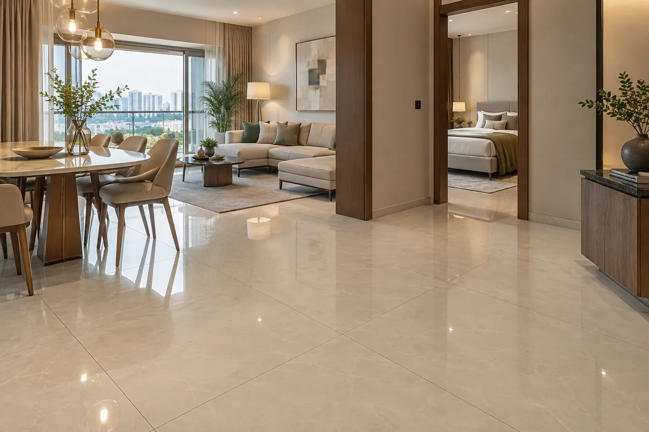
Living, dining, and bedroom areas shall feature premium mirror-polished vitrified tiles in large-format dimensions of 4′ × 2′ or 4′ × 4′, selected according to the approved interior finish schedule. Tiles shall be checked for shade consistency, dimensional accuracy, surface defects, and suitability for residential floor use before installation. Laying shall follow an approved pattern, with uniform spacer joints and coordinated alignment across adjoining spaces. The substrate shall be properly prepared and levelled, and a compatible adhesive suitable for large-format vitrified tiles shall provide the required bedding coverage. Finished surfaces shall maintain controlled edge-level differences between adjacent tiles, with neatly executed cuts at corners, doorways, and service openings. Matching grout and appropriately positioned movement joints shall complete the installation.

Kitchen & Utility Architecture

Specification 09

Kitchen & Utility Architecture

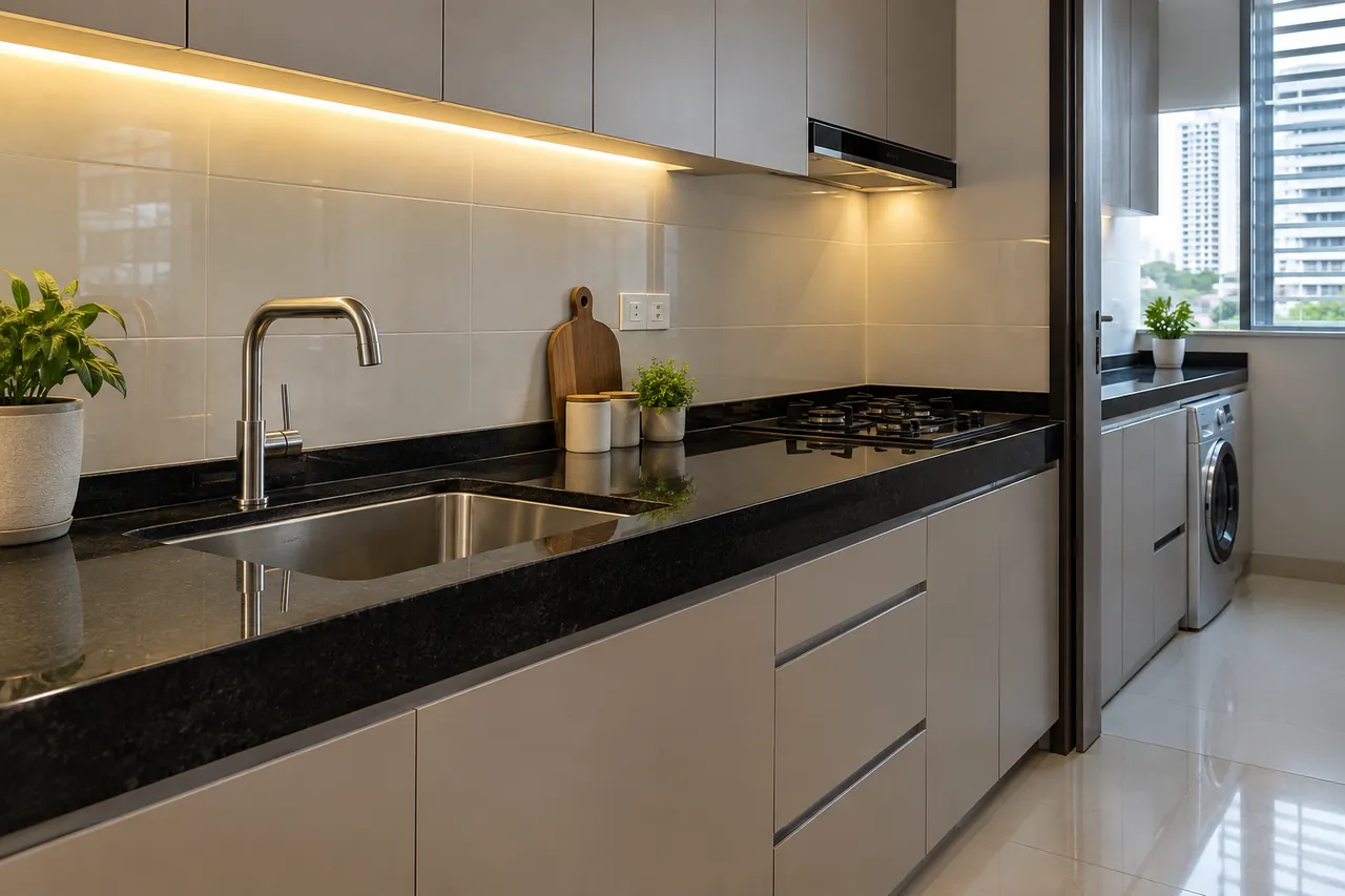
Kitchen and designated utility counters shall be finished with polished 40 mm thick Absolute Black Granite slabs, supported on an approved base suitable for the slab weight and anticipated use. Granite shall be inspected for cracks, defective edges, and unacceptable variations in appearance. Exposed edges shall receive an approved polished profile, while slab joints, wall junctions, and sink cut-outs shall be neatly finished and sealed with compatible materials. The premium integrated WPC or stainless-steel kitchen sink setup shall be detailed to identify the sink bowl material, any WPC cabinetry or supporting components, and the mounting arrangement before procurement. Sink installation shall include adequate support, sealed perimeter joints, and accessible waste connections for maintenance. Wall cladding above the counter shall comprise premium glazed ceramic tiles extending 2 feet above the finished countertop, with consistent joints and neatly finished edges around electrical outlets and plumbing points.

Bathrooms & Wet Areas

Specification 10

Bathrooms & Wet Areas

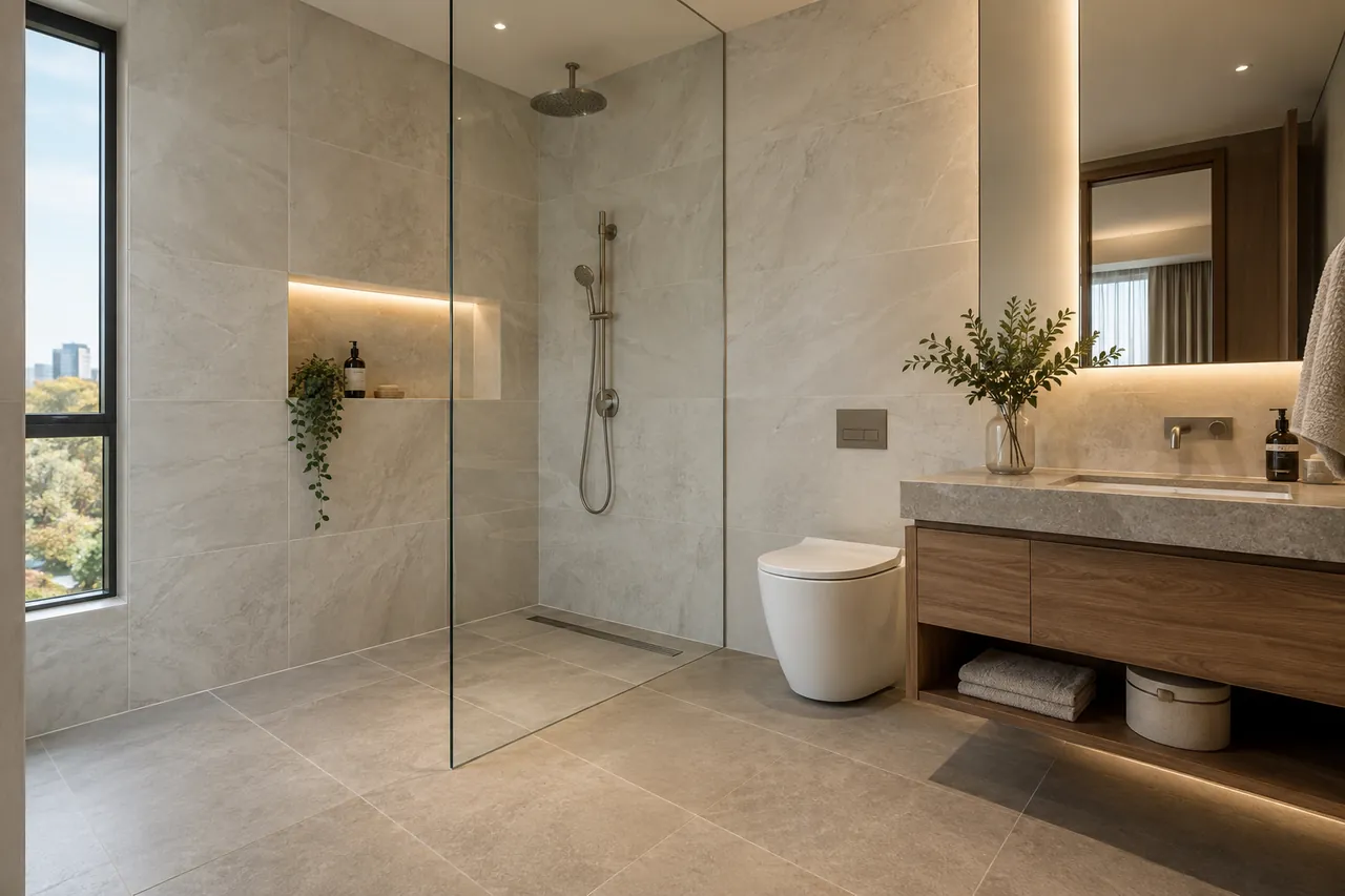
Bathroom and wet-area floors shall use slip-resistant ceramic tiles measuring 2′ × 2′, with the specified acid-washed finish subject to the tile manufacturer’s confirmation of suitability. Tile selection shall be supported by slip-resistance information appropriate to wet, barefoot use; the finish description alone shall not establish performance. Floors shall be laid to approved falls towards drainage outlets, with cuts and junctions arranged to minimise standing water. Waterproofing shall be completed, inspected, and tested before installation of the final floor and wall finishes. Walls shall receive premium glazed vitrified tile cladding measuring 2′ × 4′ or 2′ × 2′, extending to the lintel level or false-ceiling boundary, as shown on approved drawings. Compatible adhesives, moisture-resistant grout, and flexible sealant at movement joints and changes of plane shall complete the finish. Tile cladding shall serve as a surface finish rather than a structural element.

Common Areas & Stairwells

Specification 11

Common Areas & Stairwells

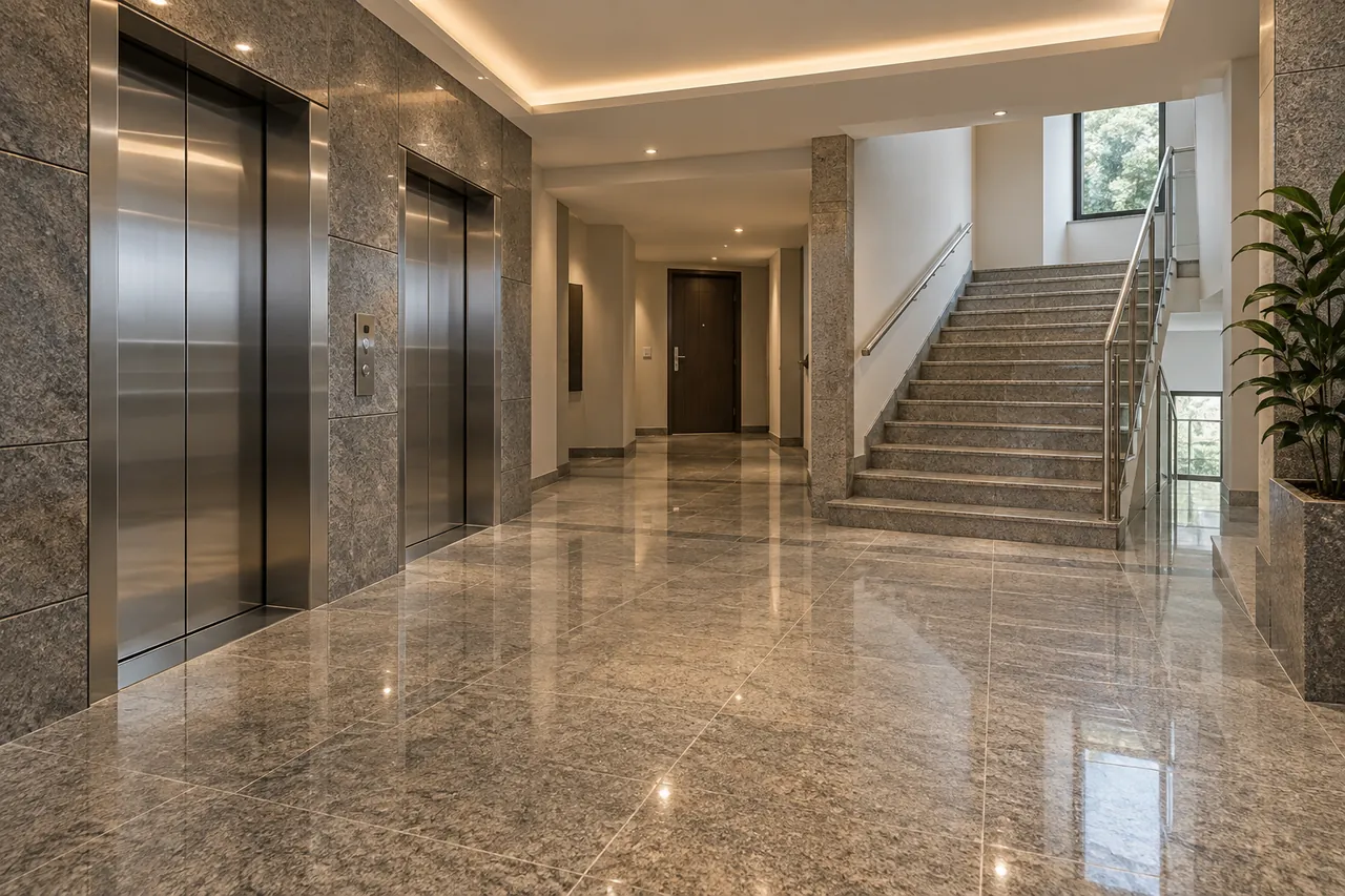
Internal common corridors, lift lobbies, stair landings, and passenger stair steps shall feature heavy-duty, mirror-finished granite slabs, selected for the anticipated pedestrian traffic and approved architectural appearance. Slab thickness, supporting base, and laying method shall suit the location and loading requirements. Granite shall be laid with consistent joint alignment, properly supported edges, and flush transitions at adjoining floor finishes and lift entrances. Stair treads and risers shall maintain the dimensions and uniformity shown on approved drawings, with neatly finished exposed edges. The polished finish shall be assessed for the required slip resistance, particularly on stairs and areas exposed to water; suitable tread finishes, slip-resistant nosings, or other approved measures shall be detailed accordingly. Completed stonework shall be checked for loose slabs, uneven edges, and defective joints before handover.

Balcony Infrastructure

Specification 12

Balcony Infrastructure

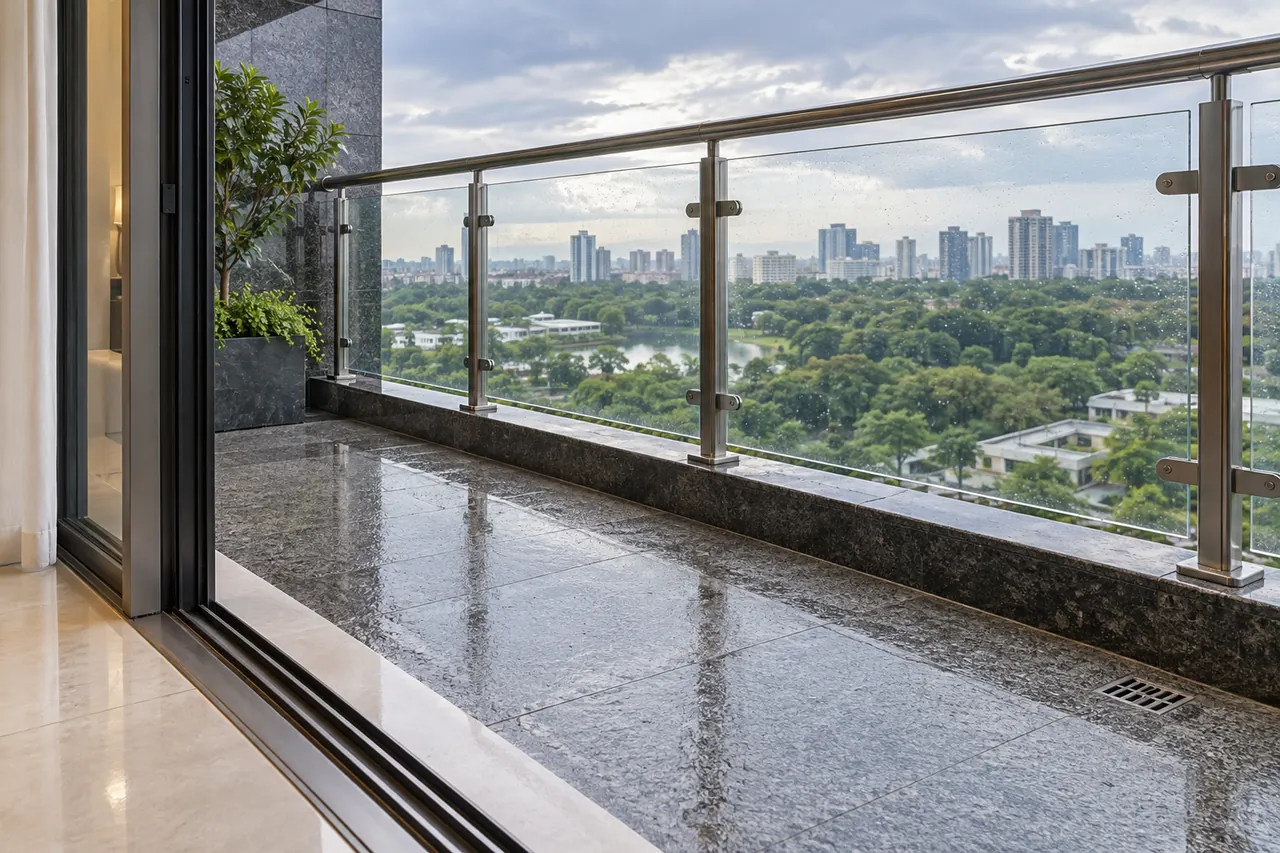
Balconies shall incorporate premium granite flooring accents, with an approved finish suitable for outdoor exposure and wet conditions. The floor build-up shall include waterproofing, appropriate falls towards outlets, and carefully sealed threshold and perimeter details. Balcony guarding shall comprise heavy-duty Stainless Steel, S.S. Grade 304, grills or railings, integrated with high-impact architectural safety glass panels. Railing height, member sizes, opening dimensions, anchorage, and glass specification shall follow the approved engineering design and applicable building requirements. Glass construction, thickness, interlayer where applicable, and support arrangements shall be selected for impact resistance and the required behaviour following breakage. Stainless-steel welds and exposed surfaces shall be neatly finished, with compatible fittings and protective measures at connections. Railing fixings shall be coordinated with the balcony waterproofing, and the completed assembly shall be inspected for secure anchorage, alignment, and exposed sharp edges.

04Electrical, Mechanical, and Utilities Infrastructure

Wiring & Conduit System

Specification 13

Wiring & Conduit System

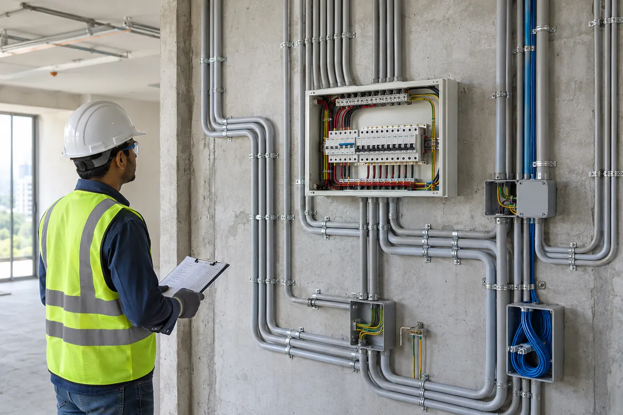
Electrical installations shall comprise concealed fire-retardant low-smoke (FRLS), multi-strand copper wiring from premium certified brands such as Finolex/Anchor/Havells or approved equivalents, routed through heavy-gauge PVC conduits. Cable sizes, circuit arrangements, and protective devices shall be selected according to the approved electrical load calculations and installation drawings. Conduits shall be securely installed with suitable bends, junction boxes, and accessible termination points to facilitate wiring and future maintenance. Power and communication cabling shall maintain the required separation. Distribution boards shall incorporate appropriately rated overload, short-circuit, and residual-current protection, together with an effective earthing system. Circuits shall be clearly labelled, and concealed cable joints shall be avoided. Insulation resistance, polarity, earth continuity, and protective-device operation shall be checked before energisation and handover.

Point Allocations

Specification 14

Point Allocations

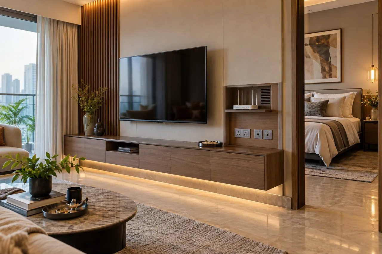
All master bedrooms and main family living lounges shall include designated provisions for high-speed Internet connectivity, dedicated router locations, telephone points, and cable TV coaxial connections. The installation shall comprise the required communication conduits, specified cabling, termination outlets, and conveniently positioned electrical sockets for associated equipment. Outlet positions shall be coordinated with the approved furniture layout, television locations, and anticipated router placement. Communication routes shall connect to an accessible apartment distribution point and the building’s service-provider entry infrastructure. Cable categories, outlet quantities, and termination arrangements shall follow the approved point schedule. Completed connections shall be labelled and tested for continuity and their specified performance. Router equipment, service activation, and subscription arrangements shall be expressly identified in the project’s supply schedule.

Integrated Intercom Matrix

Specification 15

Integrated Intercom Matrix

A centralised digital electronic intercom system shall connect every apartment directly to the main security checkpoint desks, enabling residents and security personnel to communicate for visitor verification and routine access coordination. Each apartment shall receive a compatible intercom station at an accessible location, connected to the central system through the approved communication network. The security console shall provide clear apartment identification and reliable call routing. System capacity shall accommodate all designated apartments and security stations, with suitable access for maintenance of central equipment and cabling. Backup power requirements shall be defined in the approved system design. Commissioning shall include apartment-by-apartment checks of call initiation, ringing, voice clarity, and communication with the security desks.

Sanitary and Plumbing Fixtures

Specification 16

Sanitary and Plumbing Fixtures

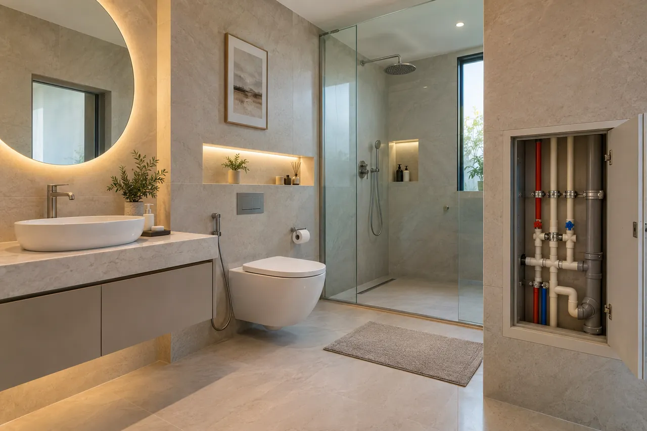
Concealed hot- and cold-water supply lines shall use pressure-rated CPVC pipes and compatible fittings, selected for the system’s operating pressure and temperature. Pipe routing, supports, jointing, and allowances for thermal movement shall follow the approved plumbing drawings and manufacturer’s installation requirements. Accessible isolation valves shall facilitate maintenance, and water-supply lines shall undergo hydrostatic pressure testing before concealment. Drainage and soil-waste pipework shall be specified separately for their intended applications. Water closets and wash basins shall be sourced from approved premium brands, while taps, overhead showers, and diverters shall be Jaquar or an approved premium equivalent. Fixture models, finishes, mounting arrangements, and operating-pressure requirements shall be coordinated with the bathroom layouts. Installations shall be checked for leakage, flushing performance, drainage, and smooth operation before handover.

Borewells

Specification 17

Borewells

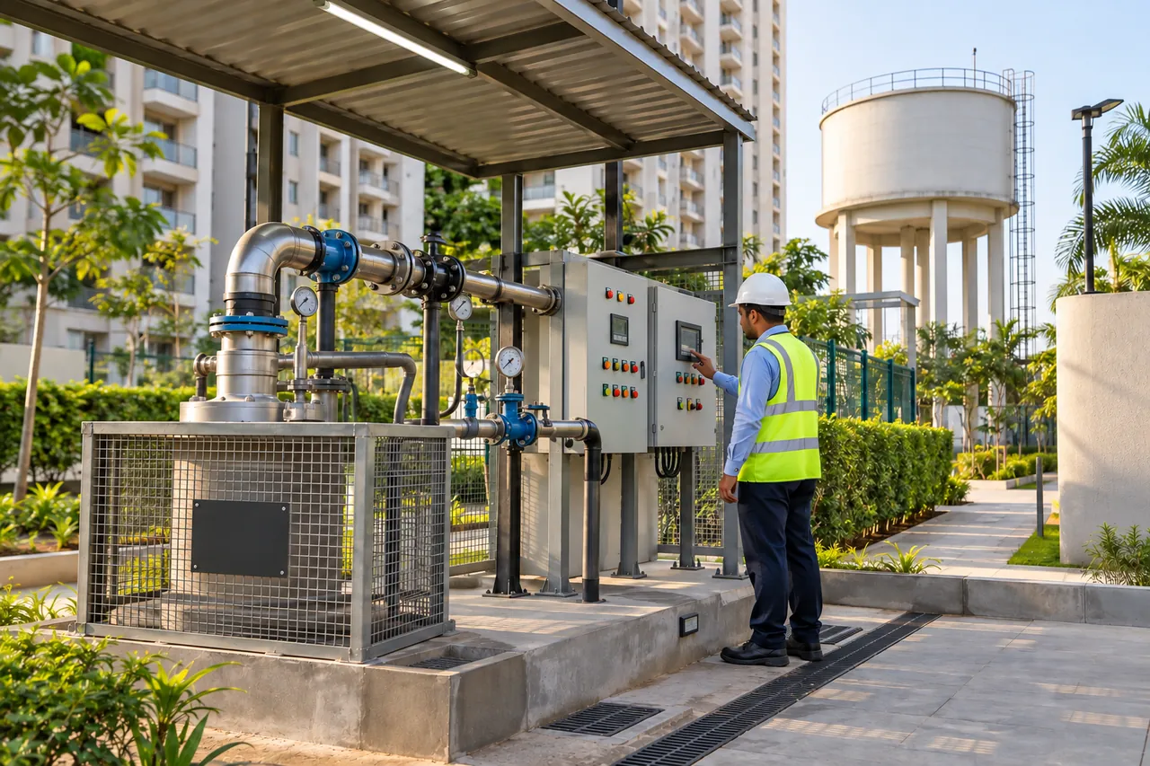
The proposed groundwater infrastructure shall comprise independently equipped deep borewells, connected to a central overhead water-storage and delivery system with automatic pump switching. Borewell locations, spacing, depths, and construction details shall be established through a site-specific hydrogeological assessment and applicable groundwater permissions. The intended high-yield performance shall be verified through pumping tests that assess discharge, drawdown, recovery, and sustainable operation; depth or borewell count alone shall not constitute a yield guarantee. Pumps shall be selected according to the tested yield and required delivery head. Controls shall incorporate appropriate tank-level sensing, pump sequencing, dry-run protection, and overflow prevention. Water quality shall be tested, with any necessary treatment determined before supply for the intended domestic use. Borewell heads, valves, and electrical controls shall remain protected and accessible for inspection and maintenance.

Central Gas System

Specification 18

Central Gas System

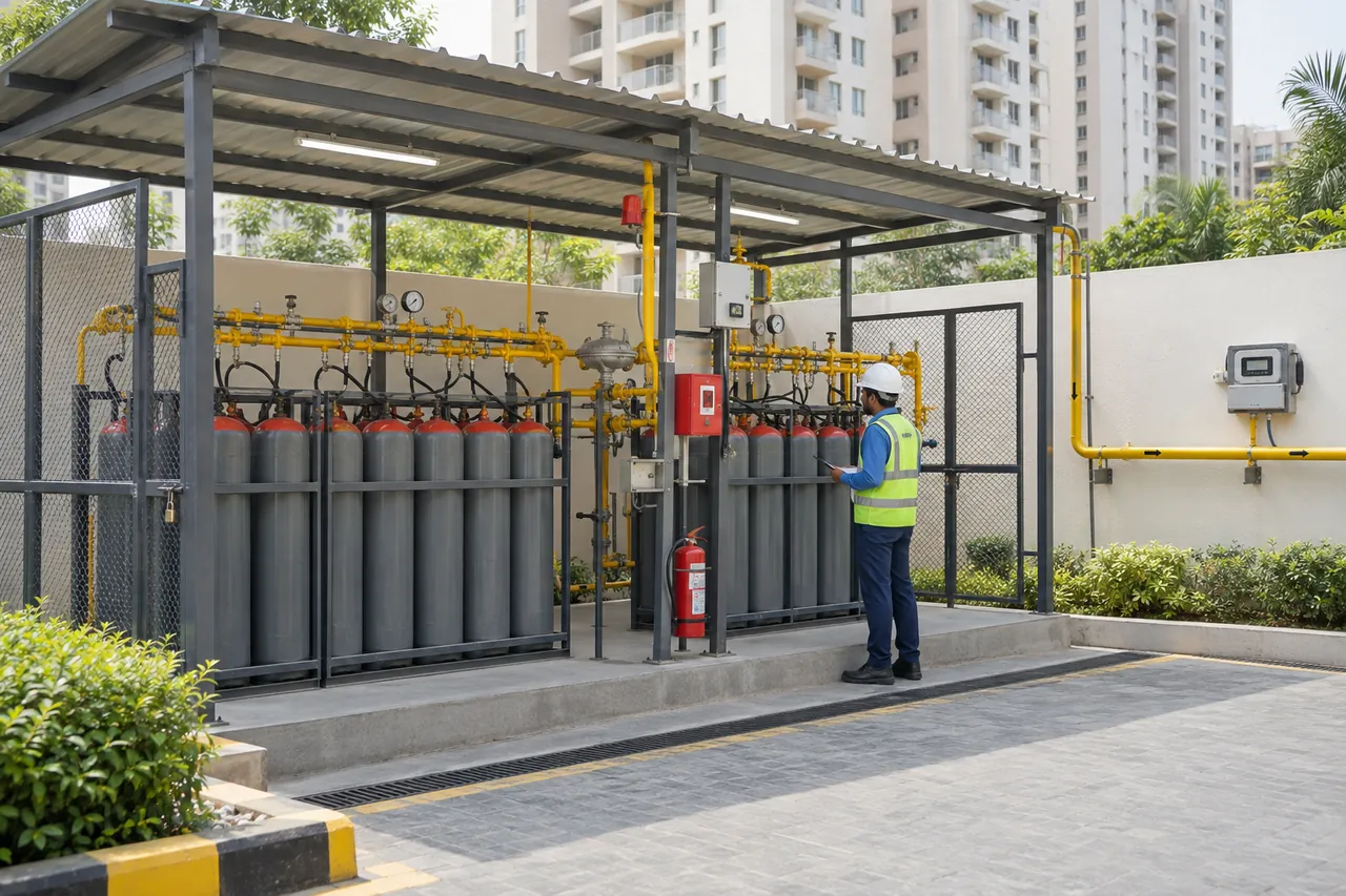
A reticulated gas distribution network shall supply individual kitchen cooktops from a centralised, protected external gas-bank compound, with apartment-level consumption managed through prepaid digital gas meters. The complete installation shall be designed and commissioned by a competent, authorised gas-system contractor in coordination with the gas supplier. Bank capacity, ventilation, separation distances, access control, pipeline routing, and fire-protection arrangements shall follow the approved design and applicable statutory requirements, including PESO permissions where required. The network shall incorporate suitable pressure regulation, accessible isolation valves, emergency shut-off arrangements, and gas-leak detection as specified by the system designer. Kitchen connections shall be compatible with the supplied gas and approved appliances. Commissioning shall include leak-tightness testing, meter verification, and checks of alarms and shutdown functions. Handover documentation shall cover recharge procedures, emergency contacts, operating instructions, and the inspection and maintenance schedule.

05Common Amenities, Safety, and Electromechanical Systems

Vertical Mobility System

Specification 19

Vertical Mobility System

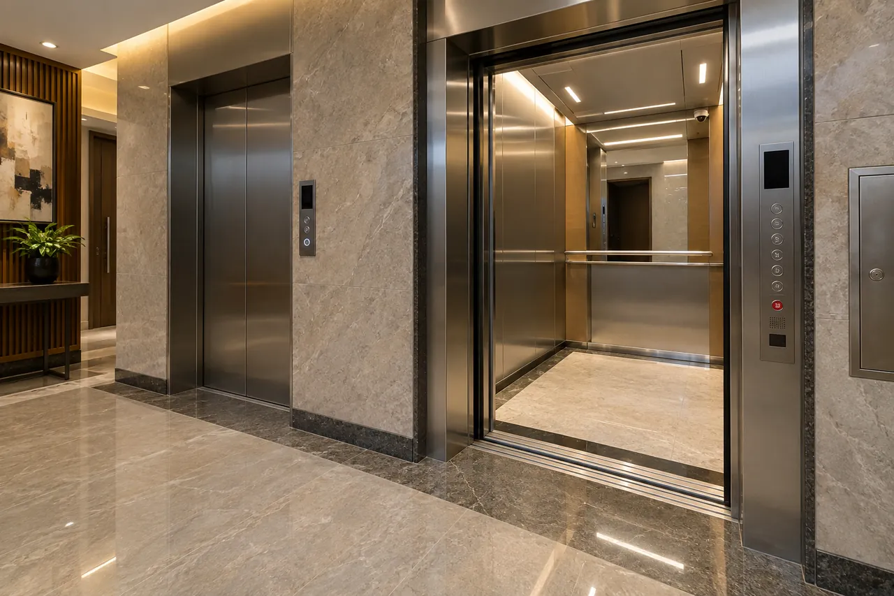
The building shall be equipped with high-speed automated passenger elevators from Johnson Lifts, with a specified internal car size of 7′ × 5′, subject to confirmation in the manufacturer’s approved layout and capacity selection. Rated passenger capacity, operating speed, door-opening dimensions, and floor coverage shall be established through the approved lift specification and building traffic assessment. Each elevator shall incorporate Automatic Rescue Devices (ARD), automatic doors with obstruction detection, emergency lighting, an alarm, and communication with the designated security or assistance point. The ARD shall facilitate controlled movement to a suitable landing and passenger release during a power failure, according to the manufacturer’s operating sequence. Dedicated lift machine rooms shall provide the required structural support, ventilation, lighting, electrical isolation, and maintenance access. Shaft dimensions, pit depth, overhead clearance, and installation tolerances shall follow Johnson Lifts’ approved drawings. Testing, statutory inspection, and operating approvals shall be completed before passenger use.

Power Backup

Specification 20

Power Backup

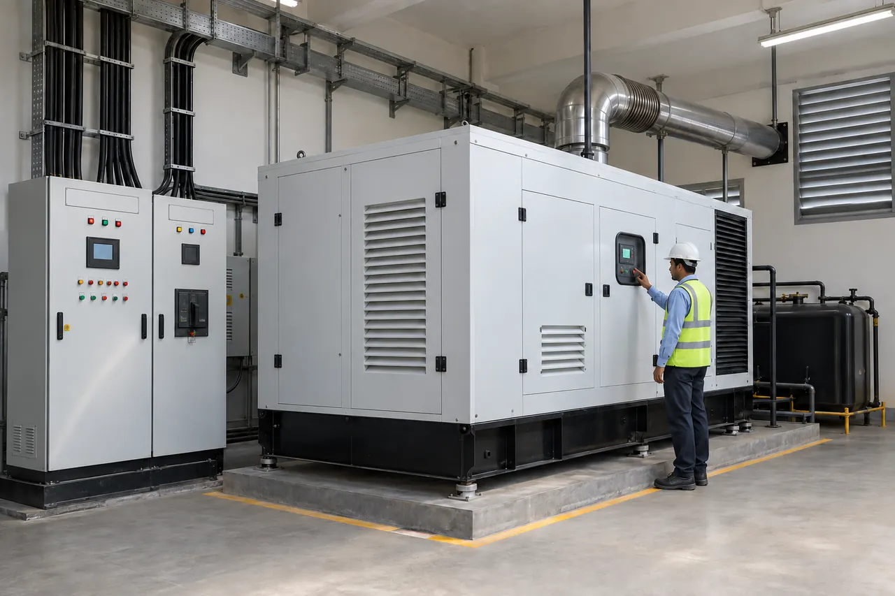
A centralised, heavy-duty Diesel Generator (DG Set) shall provide backup power to 5 designated operational power points in every 2BHK and 4BHK apartment, and 6 designated operational power points in every 3BHK apartment, together with 100% backup coverage for common lifts, pumps, corridor lighting, and perimeter security networks.
Perimeter Security Matrix

Specification 21

Perimeter Security Matrix

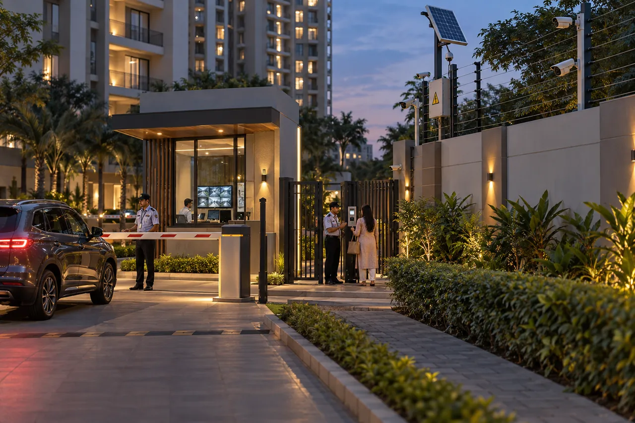
The premises shall incorporate round-the-clock physical security and electronic surveillance, supported by staffed security checkpoints, controlled entry arrangements, and CCTV coverage of designated entrances, exits, common circulation areas, and perimeter locations. Camera positioning shall suit the approved security layout while respecting private residential spaces. Panic buttons integrated with the intercom system shall transmit identifiable alerts to the security desk, with locations and response procedures established in the approved system design. The compound perimeter shall incorporate solar-powered electric security fencing, subject to local permissions, using certified, energy-limited pulsed fence energizers suitable for the application. The installation shall include appropriate warning signage, protective separation from public access, isolation facilities, and manufacturer-specified earthing and surge protection. Gate crossings and emergency exits shall be detailed to preserve safe access and evacuation. CCTV recording, alarm communication, and backup-power arrangements shall be tested before handover.

Parking Management

Specification 22

Parking Management

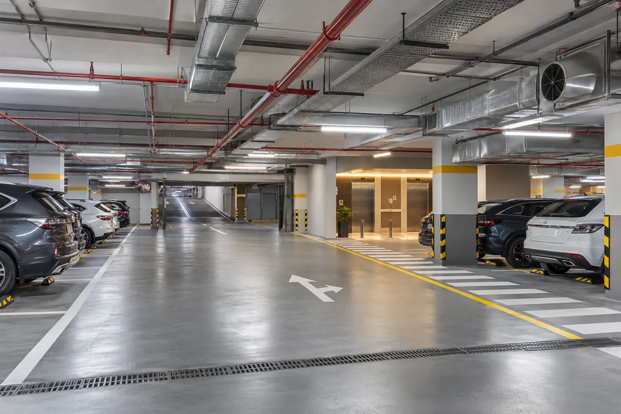
Stilt and basement parking shall follow an approved, dimensionally coordinated layout providing the designated number of allocated car spaces. Bay dimensions, driveway widths, turning areas, ramp geometry, and entry clearances shall accommodate the intended vehicle sizes and manoeuvring requirements. Clear headroom shall be verified beneath beams, pipes, ducts, cable trays, sprinklers, and other installed services, including along ramps and vehicle circulation routes. Parking spaces shall be clearly numbered and marked, with directional signs, pedestrian routes, wheel stops, and column protection where required by the layout. Finished surfaces shall provide suitable traction and drainage, with basement water collection and pumping arrangements incorporated where necessary. Lighting, ventilation, and smoke-control provisions shall be coordinated with the approved building-services and fire-safety designs. Parking allocations shall preserve access to exits, firefighting equipment, lift lobbies, and maintenance areas.

Firefighting & Life Safety Systems

Specification 23

Firefighting & Life Safety Systems

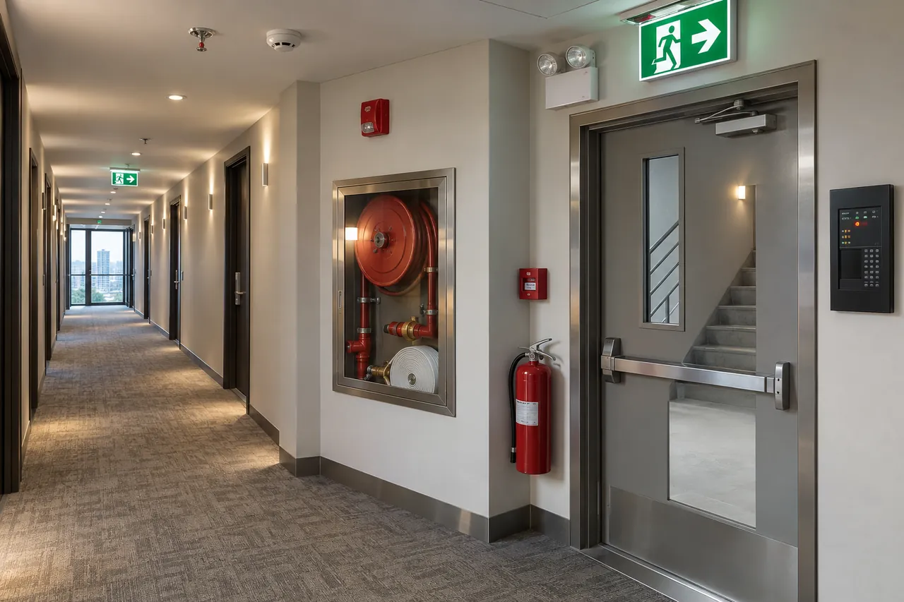
The building shall incorporate an integrated fire-protection system comprising pressurised fire hydrants with automatically controlled pumping equipment and automatic sprinkler installations, serving common corridors, residential floors, and basement levels according to the approved fire-safety layout. Dedicated firefighting water storage, pumps, pipework, valves, and fire-service connections shall be sized through the required hydraulic design. A centralised fire-alarm system shall include smoke detectors or other suitable detectors at designated locations, manual call points, and audible or visual alarm devices. The main control panel or an approved repeater panel shall be positioned at the security office or designated fire-control location for continuous monitoring. Portable fire extinguishers shall be provided on every floor, with types and locations selected for the identified hazards. Exit signage, emergency lighting, protected escape routes, fire doors, and required smoke-control systems shall be coordinated with the overall life-safety design. Installation and commissioning shall follow applicable fire-authority requirements and relevant provisions of the National Building Code, with inspection records, operating instructions, and a maintenance schedule provided at handover.